
Model the link and interfaces
Count adapters, connectors, splices and passive devices. Identify interface type, key orientation and polish.
A repeatable workflow reduces incompatible interfaces, hidden loss and incomplete commissioning records.
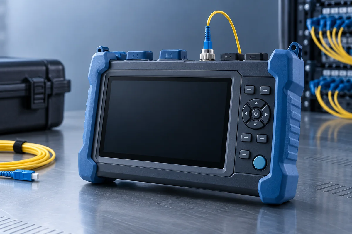
Record the endpoints, topology, route distance, required data rate, availability target, interface type, panel cut-out and expected service life before choosing an adapter or coupler.
The checklist can be applied to FTTH, enterprise, data-centre, industrial and telecom links.
Count adapters, connectors, splices and passive devices. Identify interface type, key orientation and polish.
Add specified adapter loss and cleaning allowance, then compare with the transmitter/receiver operating window.
Protect sleeve and ferrule, torque mounting screws evenly, and inspect and clean end faces before mating.
Use power/loss testing for channel acceptance and OTDR where event location or route evidence is required.
No single reading describes every aspect of a fiber optic adapter position.
Checks contamination and end-face damage before a connector is mated.
Measures end-to-end insertion loss at the selected wavelength.
Estimates event location, reflectance and distributed attenuation along a route.
Confirms mapping before equipment is connected, especially for multifiber panels.
Commissioning records should connect each measurement to the adapter identifier, panel position, endpoints, wavelength, reference method, equipment and date.
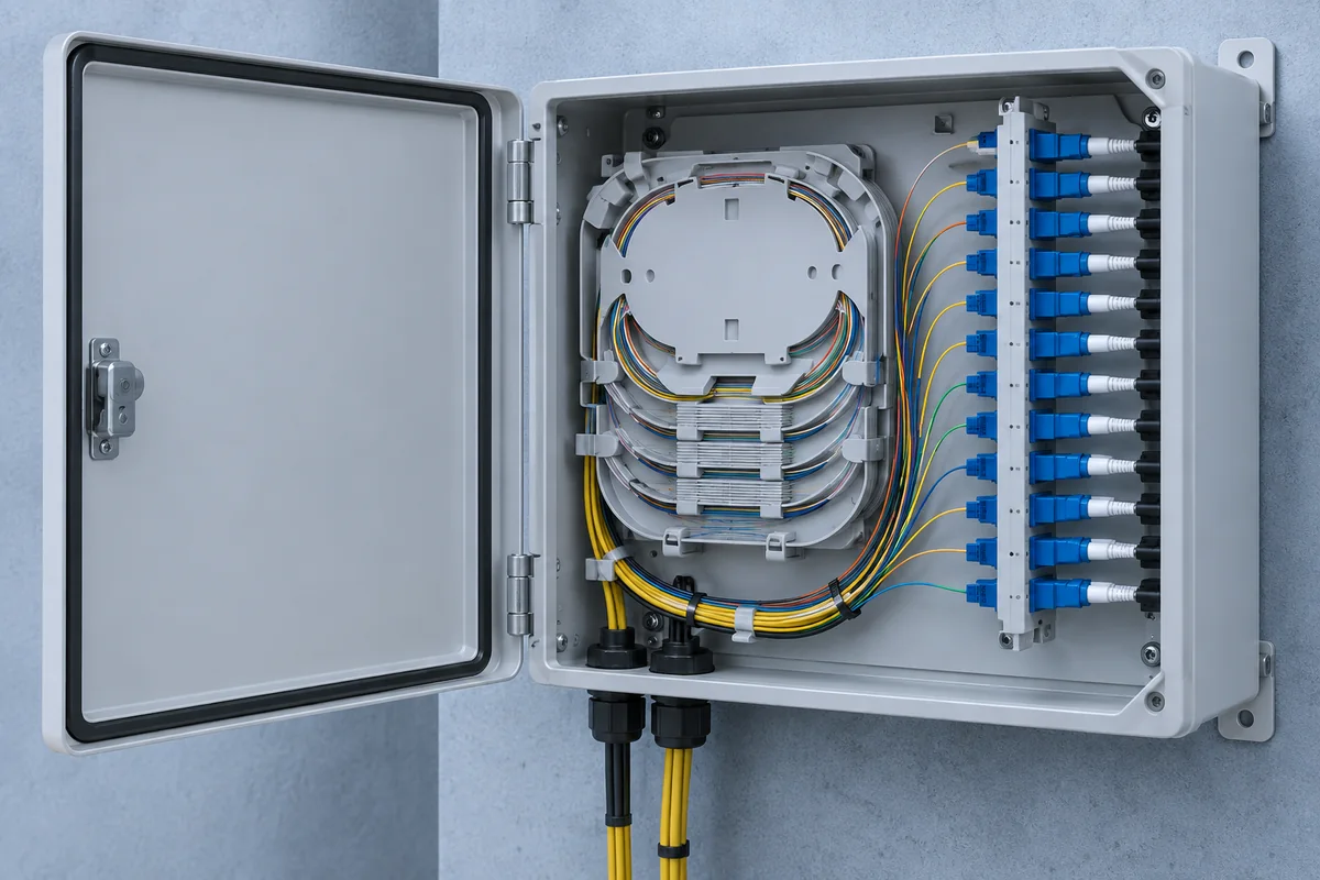
A concise technical brief makes adapter and testing discussions more useful.